INTRODUCTION
This lab section is to implement the PID control to the motors according to the yaw angle calculated by reading from the IMU sensor. Also, we learnt how to examine and substract the bias with the gyroscope.
PRELAB
Parts Required
- 1 x R/C stunt car
- 1 x SparkFun RedBoard Artemis Nano
- 1 x USB cable
- 2 x Li-Po 3.7V 650mAh (or more) battery
- 2 x Dual motor driver
- 2 x 4m ToF sensor
- 1 x 9DOF IMU sensor
- 1 x Qwiic connector
BLE
Basically, the structure is similar to the previous lab. However, I have made several changes, since it is unstable to just put the PID control algorithm in the CASE program inside the handler. Hence, I have created a structure in the main loop, which is controlled by the flag called, pid_orientation_on.
Firstly, I define the following array to store the data, which will be sent to the laptop later.
Also, I use these command to start the PID orientation control on the robot through BLE:
Hence, with the data sent through the channel, it can be received by the laptop and plot in the figure by the following code. The first block is for receiving the data sent from the Artemis, and the second block is for plotting the data into the diagram to debug and show the results.
LAB TASKS
P/I/D discussion
As it is stated in the lab section, the PID controller is comprised of three part, propotional, integral and derivative. Therefore, the equation can be represented as:
\( \text{correction} = K_p \cdot \text{error} + K_i \cdot \text{integral error} + K_d \cdot \text{derivative error} \)
The proportional gain, Kp, adjusts the current error (the gap between the desired and actual values) in proportion to its magnitude. A higher Kp intensifies the corrective action, yet it may lead to instability or overshooting.
The integral gain, Ki, addresses accumulated past errors. It amplifies the corrective action when the error persists over time, but excessive Ki values can result in overshooting or weaving due to the gradual reduction of accumulated errors.
The derivative gain, Kd, anticipates future errors by assessing the rate of error change. It serves as a damping mechanism to minimize overshooting and moderate the speed of corrective actions, although it may also amplify noise.
Modification
To make the system more stable, I put all the PID control code in the main loop, instead of putting them into the CASE handler.
Range/Sampling time discussion
The reading frequency of the IMU is relatively slow, compared to the TOF, so it will be fine if no extrapolation implemented.
Implementation
Since the gyroscope has a bias in its measurement, we should calculate the bias parameter at the setup of the Artemis, ensuring that the IMU reading will not lose its accuracy as time goes by.
This section shows the implementation of the orientation PID control of the robot, which is based on the setup angle and the current angle read by the IMU sensor. The following code demonstrate the PID controlling routine in the main loop.
Where the pid_orientation() function is shown below, with the wind-up protection implemented:
And where the start_record flag is set to true, when the command is given.
Furthermore, if the record is started, indicated by the flag start_record, we will record all the data into defined arrays by increasing pid_orien_num which cannot be exceeding orien_num, with the value of 1000.
In the orientation PID controlling starting handler, the value of Kp, Ki, Kd, target_angle will be stored for further processing.
After all the recording is completed, the data will be sent over the BLE channel by implementing the command ble.send_command(CMD.SEND_ORIENTATION_DATA, ""), where the handler on the Artemis side is shown as below:
Graph data results
With the command sent through the BLE channel, we can observe that the robot return to the setting angle, when external force push it to other angles.
Additionally, we can set the target angles to several different values within a certain interval.
Thus, the result is demonstrated in the video below:
When the wind-up protection value is like below:
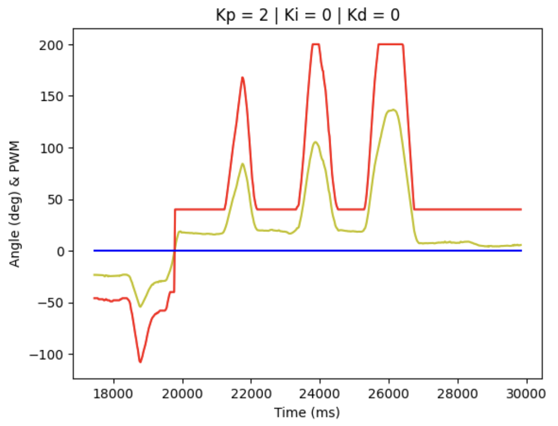
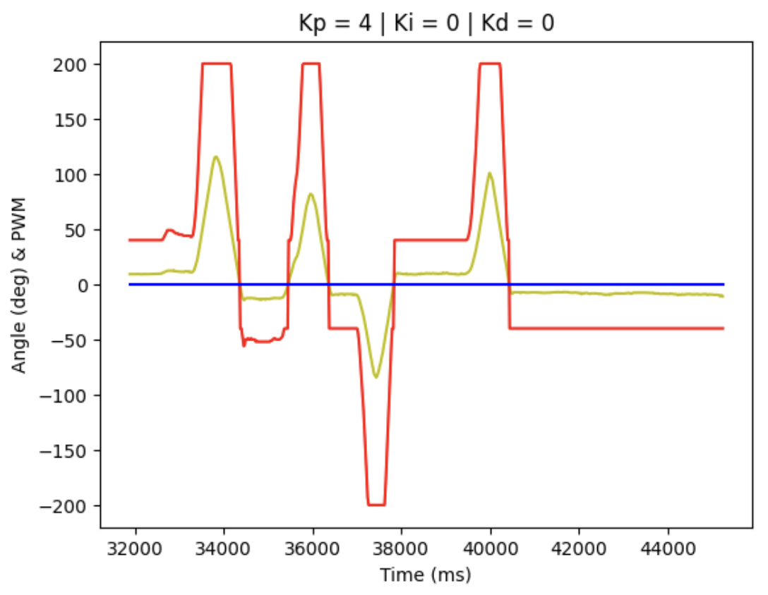
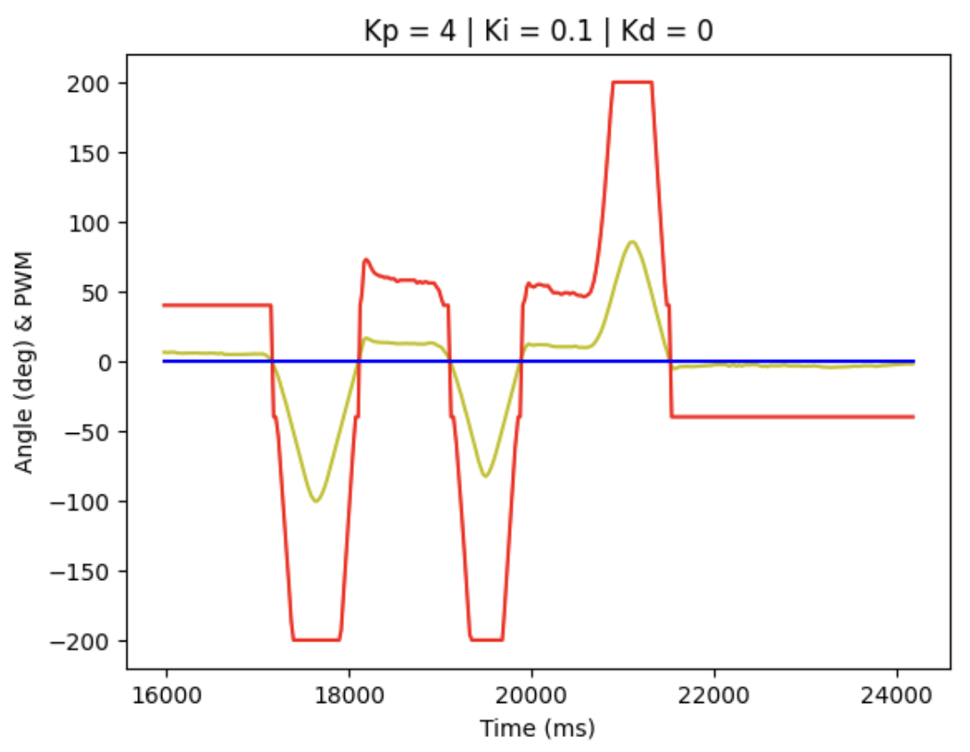
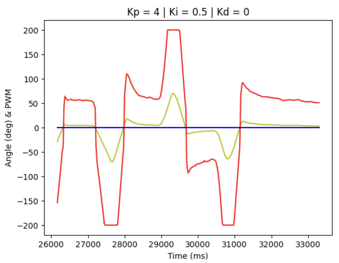
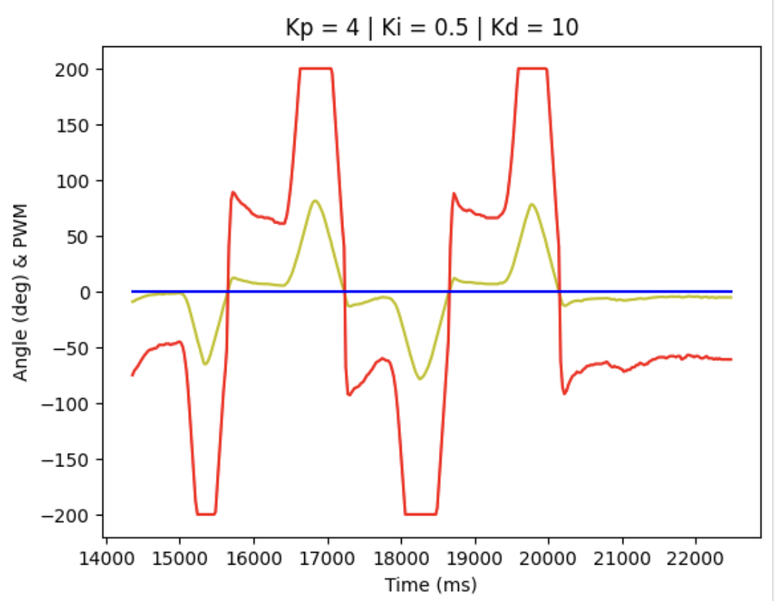
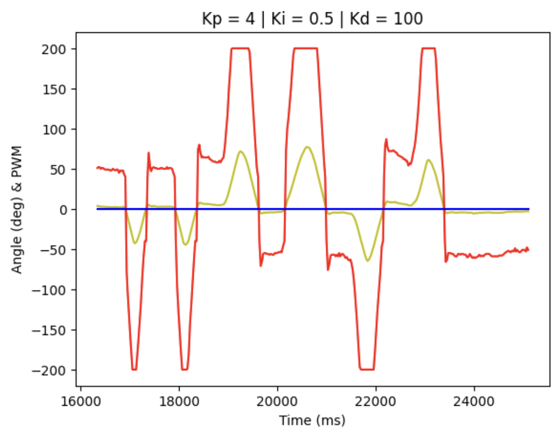
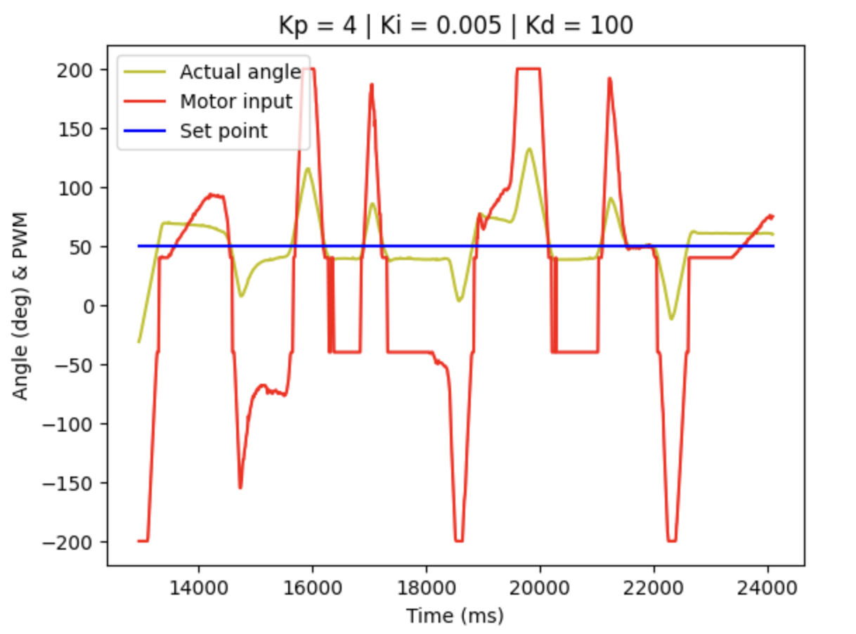
We can record the data arrays and obtain the plotting figure for debugging and tuning the PID parameters, where blue line represent for set point, red line for PWM motor input signal and yellow for actual angle detected.
When Kp = 2, Ki = 0, Kd = 0, the diagram is shown below:
When Kp = 4, Ki = 0, Kd = 0, the diagram is shown below:
When Kp = 4, Ki = 0.1, Kd = 0, the diagram is shown below:
When Kp = 4, Ki = 0.5, Kd = 0, the diagram is shown below:
When Kp = 4, Ki = 0.5, Kd = 10, the diagram is shown below:
When Kp = 4, Ki = 0.5, Kd = 100, the diagram is shown below:
When Kp = 4, Ki = 0.3, Kd = 100, the diagram is shown below:
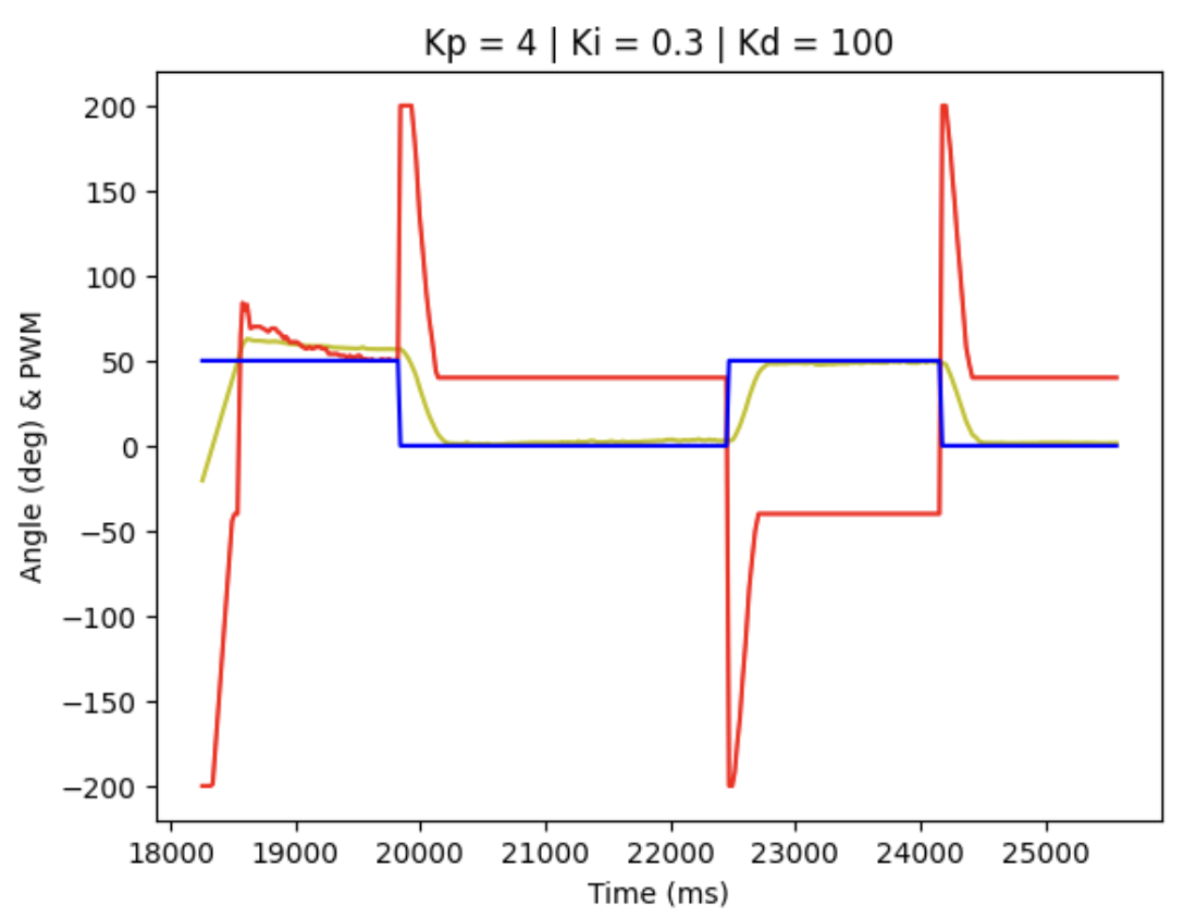
Accordingly, it can be concluded that with only P control term, the actual angle deviation from the theoretical value is too large, while with all the PID terms implemented, the control system is more accurate, since we can see from the figure above that the yellow line almost overlap with the blue line, but there is still some delay in the response.
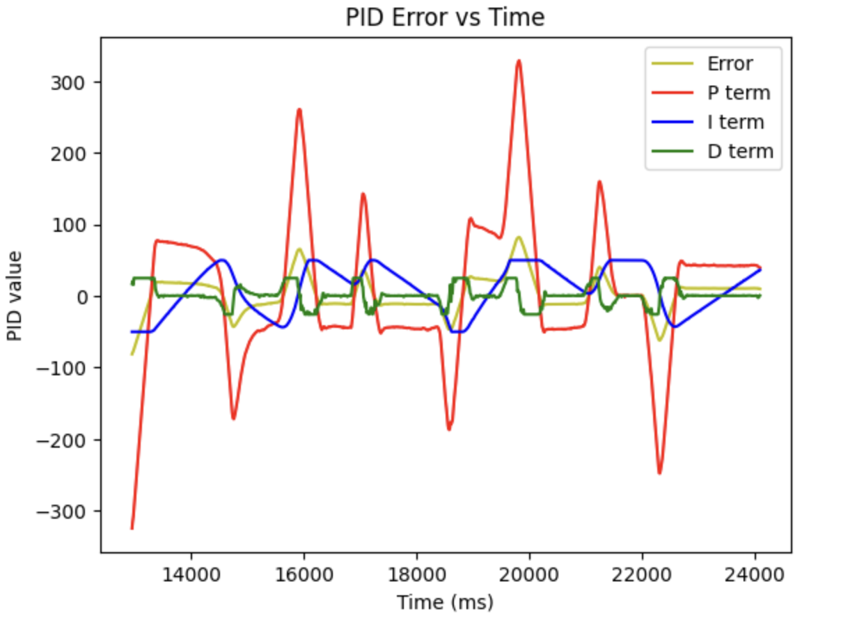
With this issue raised, I create the program to send all the PID data separately to determine the best value for Kp, Ki, Kd. Consequently, the figure below shows that the I term is always capped, which might cause some problems to the controller.
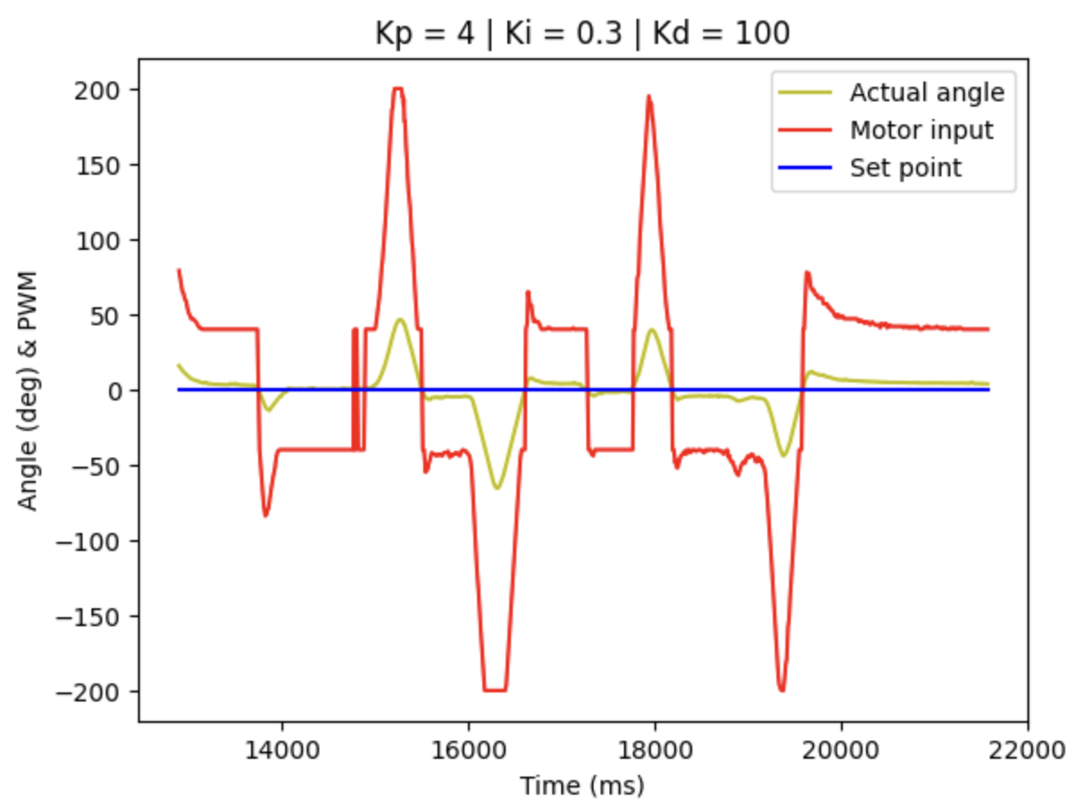
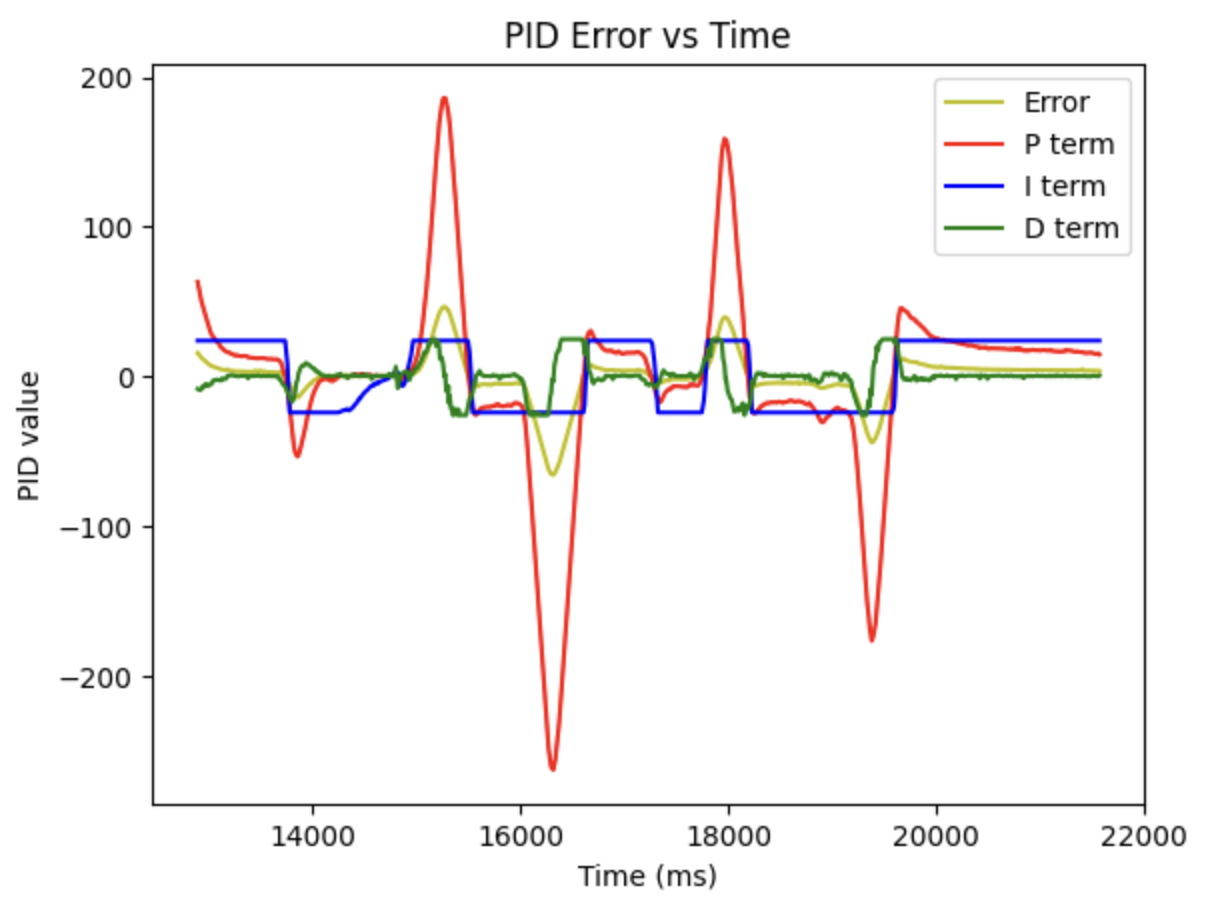
Therefore, the max wind-up value is adjusted from 80 to 10,000, as 10,000 x 0.005 = 50, which will be the proper range of the I term.
With the modification, we get the figure as shown below, in which we can see that the I term react more reasonable.
Wind-up protection
Wind-up protection is an essential feature of PID controller, particularly in systems susceptible to integrator wind-up. Integrator wind-up arises when the integral component accumulates excessively due to prolonged error conditions, resulting in issues like overshooting, instability, or other undesirable system behaviors.
In this lab, the wind-up value scale is not chosen properly, which make the I term always be capped. Therefore, I have leart that I should calculate the range of the I term first, according to the euqation:
\( \text{I term} = K_i \cdot \text{integral error} \)
DISCUSSION
In this lab, we learnt how to implement the PID controller to the motor according to the IMU sensor, and we realize the function that the robot can main the custimized angle. Furthermore, the range of the integral component of the PID comtrol should be carefully considered.
