INTRODUCTION
This lab section is to setup the Artemis board and make the Bluetooth configuration. Firstly, the familiarity of Arduino IDE and demonstration of the example codes helps us learn the basic functions. Moreover, Bluetooth Low Energy (BLE) connection will be setup in lab 2 and it is beneficial to further control of the microcontrollor.
PRELAB
Setup
Equipment:
- 1 x SparkFun RedBoard Artemis Nano
- 1 x USB C-to-C or A-to-C cable
Board Setup:
After the the installation of Arduino IDE, the Artemis board can be setup through the Sparkfun guide. Furthmore, there are several example codes that can be used to get familiar with the functions.
a. Example1: Blink It Up
In the basics section, there is a 'Blinky' example, with which the demonstration is shown below.
b. Example2: Serial Read
In the serial read algorithm, any characters can be typed into the serial window and the MCU will return exactly the same string. For instance, the word 'hello!'was input in this case, so the serial port got the same word.
c. Example3: Temperature Sensor
The third example is the temperature readings, where the code 'analogRead' can be uploaded into the Artemis.
d. Example4: PDM
In this example, the voice can be capture by the PDM with certain frequency displayed in the serial monitor. For the additional task, the following code can be added:
With the modified code, the result is shown in the video. When the musical A note is playing, the LED will be turned on.
Bluetooth Setup:
After the installation of ArduinoBLE library, the Bluetooth UUID can be generated by the following code.
Furthermore, the Artemis MAC address is shown in the serial monitor port on Arduino IDE. Therefore, the BLE_UUID_TEST_SERVICE in ble_arduino.ino and ble_service in connections.yaml can be changed according to the specific UUID.

Codebase
The codebase downloaded contains Python and Arduino files, which set up the base of BLE connection. Especially, in demo.ipynb Jupyter notebook,it includes the instruction of how to connect Artemis with the laptops through BLE and the fundamentals of notification handler.
LAB TASKS
A. ECHO Command
Task 1 is to make the robot send the same message which comes from the laptop. Therefore, the initial step is establishing the ECHO case in the MCU.
And then, the following code block can be run through Jupyter notebook, showing the reply message 'Robot says -> HiHello'.

B. GET_TIME_MILLIS Command
To get the time message, the function millis() can be applied to extract the current time. Consequently, the GET_TIME_MILLIS case on the Artemis side is shown below.
With the case established properly, the time can be recorded as 'T: 8322'

C. Notification Handler
The third task is to create a notification handler by implementing ble.start_notify(), which can continuously and automatically receive time data.
D. Time Data with Notification Handler
To make the function clearer, it is required to add another case in Arduino. GET_TIME_MILLIS_5s stands for sending time data seperately to the laptop.
With the notification handler established, the laptop can record the data in an array by time_stamp.append().

E. SEND_TIME_DATA Command
In this task, an array was created to store the time stamps, and after a certain amount of time, the data array would be sent to the laptop.
The results were shown in below, where all the time stamps were printed out in the Jupyter notebook.

F. GET_TEMP_READINGS Command
An second array was established to get the temperature data and send back to the laptop, where the temperature data was corresponding to the time that it was recorded.
The following is the data printed out. It can be concluded that sending data seperately might cause imprecise time stamps, while recording first would maintain the accuracy of the time data.

It is shown that the shortest interval between two sending time data is almost with a millisecond. Additionally, as calculated, the Artemis can store 98,304 int or float elements, or 393,216 char elements
G. Data Rate
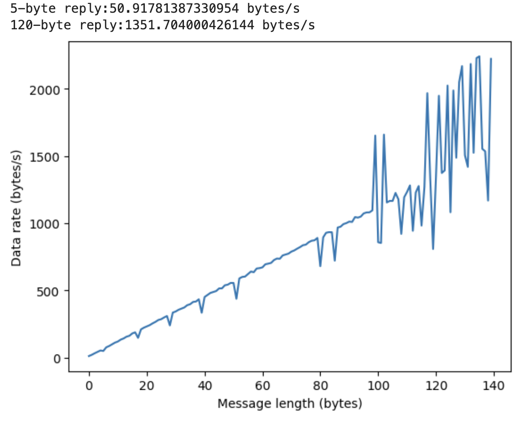
In the additional task, the data rate should be calculated to demonstrate the speed of the BLE connection channel concerning the number of replying bytes. SEND_DATA case was created to implement different byte number according to the command sent from the laptop.
The command ble.send_command(CMD.SEND_DATA, byte_num) can be implemented to get different length of reply, where byte_num can be determined as 5 or 120.
To illustrate the tendency more clearly, the plot() function was implemented to visualize the data_rate array. Therefore, it can be observed that larger replies can help to reduce the overhead generally.

H. Reliability
The reliability can be determined by printing out the number of message sent from the Artemis and to the laptop, so the Python code was generated as below:
It can be observed from the video that the system maintains high reliability as the number of message was exactly the same.
DISCUSSION
In this lab section, I have learn how to set up the Artemis board to implement the Bluetooth Low Energy connection. Furthermore, the Jupyter Notebook is introduced to manage all the written code, which is of great beneficial. However, apart from all the knowledge I have learnt, there were many challenges encountered. For instance, I basically modified the write_data() function to realize the time data sending, which would complexify the algorithm. Later, it was learnt that the easiest way to establish the function was to add more commands in the case module to complete those tasks. In addition, the notification handler can enhance the robustness of the data transmission, which I did not get command of and failed to implement in the Python code. In conclusion, this lab provided the fundamentalsof BLE and got us prepared for further implementation of the robots.
