INTRODUCTION
This lab is to implement the open loop control of the car, which uses the Artemis and the two dual motor drivers. Furthermore, it is learnt that how to apply the PWM pins to generate signals, making the motor move forward and backward.
PRELAB
Parts Required
- 1 x SparkFun RedBoard Artemis Nano
- 1 x USB cable
- 1 x 9DOF IMU sensor
- 2 x 4m ToF sensor
- 1 x QWIIC Breakout board
- 2 x Qwiic connector
- 1 x JST2 connector+cable
- 1 x Force1 RC car
- 1 x Li-Ion 3.7V 850mAh battery
- 2 x Dual motor drivers
Wiring
It is shown in the Artemis pinout diagram that the pins with PWM function have the sign '~'. Hence, the pin 13, 14, 15, 16 can be used for the motor control.

The diagram for the Motor Driver connection is shown as below, where we should use separate batteries for the Artemis and the Motor Driver.

Battery Discussion
Two batteries should be implemented in this lab, as separate power supplies with different ground references for motor drivers and microcontrollers are utilized to ensure operational stability and protect sensitive components. Furthermore, the noise can be greatly reduced, since the motors will generate electrial noises, interfering with the microcontroller operation. With this reason, two 3.7V batteries will be applied.
LAB TASKS
i. Motor driver tests
First, we can hook up the Artemis and the motor driver like this, and in this way, we can test one single motor. The power supply of the Motor Driver is simulated by the Power Generator which is set to 3.7V and the Artemis can be powered by the laptop through USB-C cable.
As the power supply of the motor drivers is 3.7V, so the pin VIN and GND should be hooked up to the Power Generator. Moreover, the Artemis can be powered by the USB-C cable through laptop.
With all the setup above, the output of the motor control pin on the Artemis can be initialized by the command analogWrite(AB1IN_LEFT,63); and analogWrite(AB2IN_LEFT,0); where AB1IN_LEFT, AB2IN_LEFT is defined as 13, A14 After this, the oscilloscope image can be obtained as shown below. The number of 63 indicates that the duty cycle is 25%, so it is corresponding to the result on the left. Later, it is changed to the value of 127, representing 75%. As I soldered the wire to the DC motor before I test it with the oscilloscope, there was a tiny distortion on the figure, maybe caused by the motion of the motor, so that it was not exactly flat when the signal was high.
ii. Wheels spinning
The following code is for testing one single motor:
Therefore, one motor spinning is shown in this video below:
Then, it is tried to implement two motor drivers, where pins are defined and the processes are created as below:
Hence, we can get two motors working properly.
iii. Connection
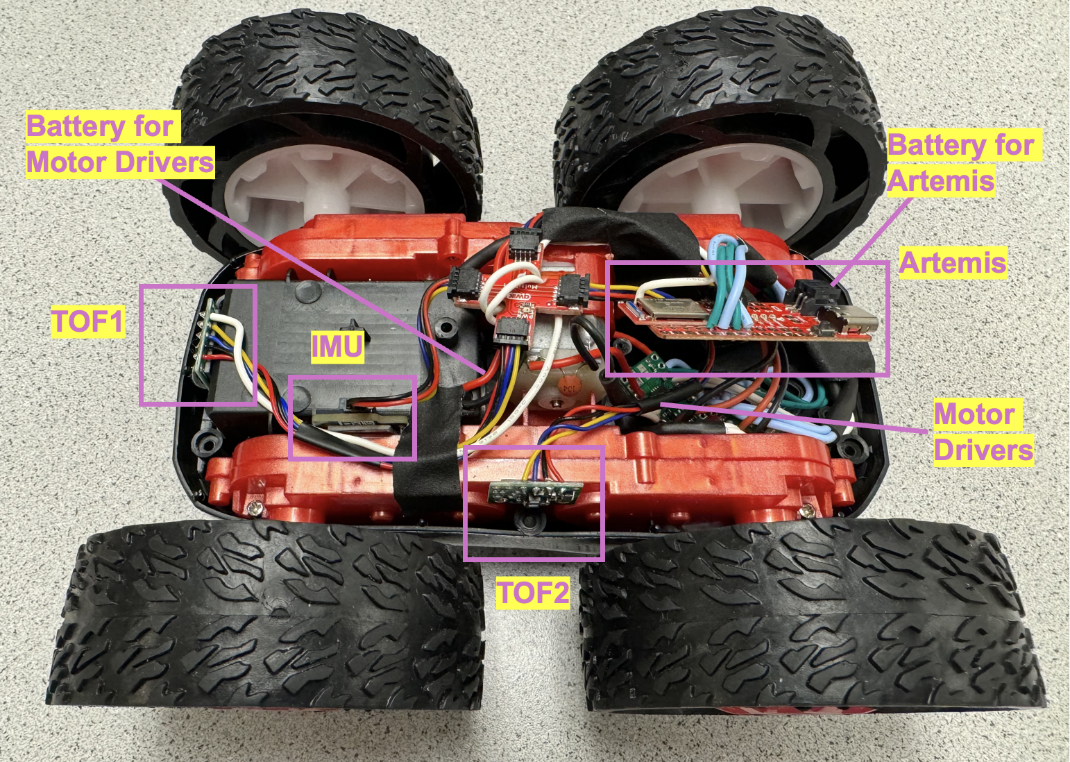
After the testing for the motor drivers and the power supply, the whole connection diagram is illustrated in the figure. Two TOF sensors are placed in the front and the side separately and the IMU is placed in the gap of the robot chassis. Furthermore, I use the tape to tidy up the cables and wires.

iv. Two Motors and Powored by Batteries.
With all the testing and soldering completed, the robot can be powered by the two batteries, and the operation is displayed in the video.
v. Lower Limit PWM
In this section, we will explore the lower limit in PWM value for making the robot moving forward on the ground, and it is shown that the lower PWM limit is 28.
This video demonstrate the motion of the robot with lower PWM value.
vi. Calibration for Going Straight Line
Since it is only the open loop control, those two motors will have different speed. Therefore, a calibration factor is implemented to make the robot move in a relatively straight line, where the factor is euqual to 1.8 in this circumstance.
It can be concluded in the video that the robot can move almost in a straight line with the implementation of the calibration factor.
vii. Open Loop Control
Then, a series of open loop control commands are implemented, by using forward(), backward(), stop(), turn_left(), turn_right.
Therefore, we get the robot motion which is demonstrated in the following video.
viii. Frequency
To analyze the frequency that analogWrite() generates, we can write a program as below to display the analog write delay time.
It is illustrated in the previous lab that TOF delay time is 8ms (125Hz), IMU delay time is 33ms (30Hz), and as it is shown in this figure, the delay time of motor control is 5ms (200Hz). Consequently, the frequency of analog write is sufficient, since the default PWM frequency is 490Hz for most of the board, and it is also adequate for TOF and IMU based control. However, the manual adjustment for the PWM can enhance the efficiency and reduce the noises.

ix. Lowest PWM value speed
To figure out the PWM value for making the robot keep moving in its slowest speed, we can implement the following program, where the blinking LED indicates every deduction of the speed so that the specific value can be obtained.
It is shown in the video that there are totally two blinks before the robot is stopped. Therefore, the PWM value is 24.
DISCUSSION
In this lab section, we learnt how to solder and assemble all the components in the robots. Furthermore, with the tests for the motor drivers and batteries, the open loop control of the motors is implemented to realize the car motion.
